
JRC Tech Seminar Vol.2
Hello everyone, do you like our last blog? You can review the previous content through the following link.
https://www.jrclte.com/blogs/jrc-tech-seminar-vol.2-introduction-of-radio-communication-part-1
Now let's continue with the seminar about Radio Communication! In this time, we will focus on the following four sections.
- Matching and Reflection
- Coaxial Cable and Connector
- Antenna
- Radio Equipment
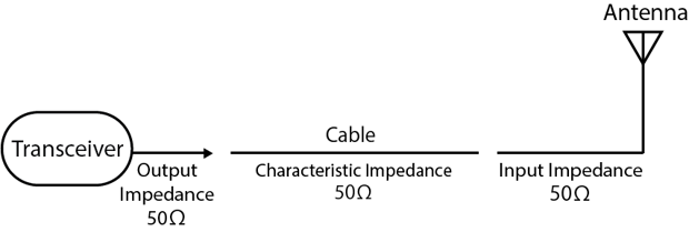
Matching and Reflection
When all the impedances match as shown in the figure below, the system is said to be matched.
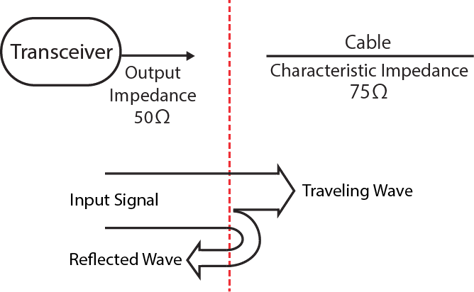
When the impedances are not matched
These traveling waves and reflected waves add up and cancel each other out, creating waves in amplitude.
The ratio of the maximum and minimum of these waves is called the voltage standing wave ratio (V.S.W.R).
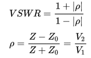
The ratio of the reflected wave to the input signal is expressed in dB and is called the reflection loss (return loss).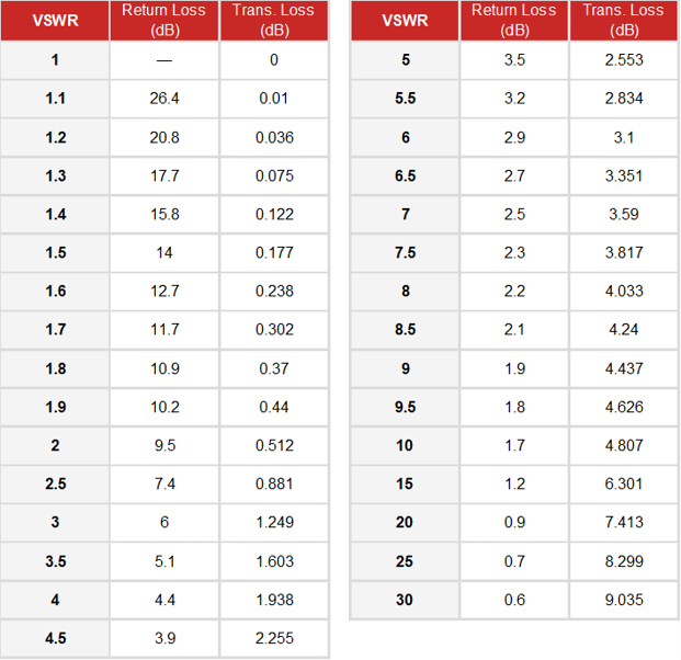
Coaxial Cable and Connector
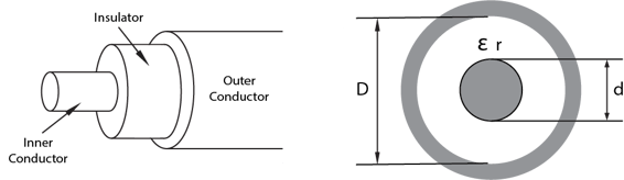
A coaxial cable contains two wires, one in the center of the cable and the other covering the center of the cable. Generally, the wire in the center is called the "center conductor" or "core wire," and the wire covering the center conductor is called the "outer conductor".
When the outer diameter of the inner conductor is d, the inner diameter of the outer conductor is D, and the relative permittivity of the insulator is εr, the characteristic impedance is given by the following equation.
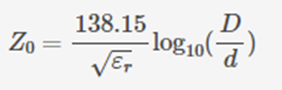
In the telecommunications industry, cables with a characteristic impedance of 50Ω or 75Ω are often used. There are a wide variety of cables, and different materials use different frequencies and have different losses.
Antenna
Antennas have two major characteristics: directivity and gain.
Directionality is a property of the direction in which radio waves fly or be received.
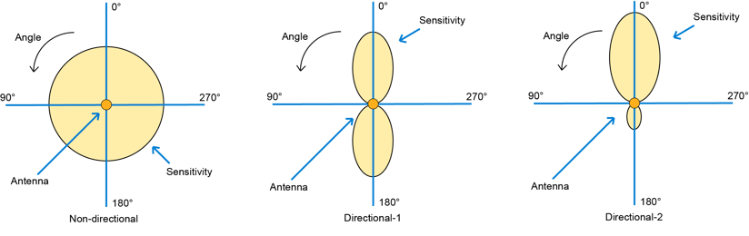
Antenna gain is a quantification of how much strength an antenna can output in relation to the strength of the radio waves it receives (transmits).
Isotropic antenna
A hypothetical antenna that does not actually exist, is a theoretical antenna that, by calculation, radiates the same strength radio waves in all-electric field strength directions.
λ/2 dipole antenna
An antenna that is half the length of the wavelength of the frequency used (λ/2) is considered to be the most efficient. When compared to a dipole antenna, it is expressed as an antenna gain of xxdB. If an isotropic antenna is used as a reference, it is expressed as antenna gain xxdBi (i: isotropic antenna). In this case, the dipole antenna gain is 0dB = 2.14dBi.
Radio Equipment
Modulation
| Method | Type | Applications/Features | Mobile Phone |
| Analog Modulation | AM: Amplitude Modulation | AM broadcasting, short-wave broadcasting | |
| FM: Frequency Modulation | FM broadcasting, community broadcasting | 1G | |
| PM: Phase Modulation | Widely applied as PSK with digital modulation | ||
| Digital Modulation | ASK: Amplitude Shift Keying | Represents 1 or 0 of a digital signal by the difference in amplitude | |
| FSK: Frequency Shift Keying |
LMR, Power efficiency is better because class-C amplifiers can be used |
||
| PSK: Phase Shift Keying | Widely used for digital modulation such as BPSK, QPSK, n/4-QPSK, etc. | 2G, 3G | |
| QAM: Quadrature Amplitude Modulation | Highly efficient digital modulation methods such as 16QAM, 64QAM, 256QAM | 4G |
Access Method
FDMA (Frequency Division Multiple Access). FDMA is a wireless access method that divides a fixed frequency band into narrower frequency bands (channels) that can be efficiently shared by multiple users. FDMA was used in the past for analog mobile phone service and is also used in today's wireless LANs.
TDMA (Time Division Multiple Access) allows efficient communication by dividing the frequency in time and allocating it to multiple users. This TDMA method is used in 2G PDC (Personal Digital Cellular), which was standardized in Japan, and GSM (Global System for Mobile Communications) in Europe and the United States.
CDMA (Code Division Multiple Access) allows multiple users to share the same frequency and time axis in the same frequency band. Each audio signal is assigned a different code for transmission and reception. CDMA is used in 3G mobile phone services such as W-CDMA and CDMA2000, which are currently mainstream because they can communicate more efficiently than TDMA and FDMA methods.
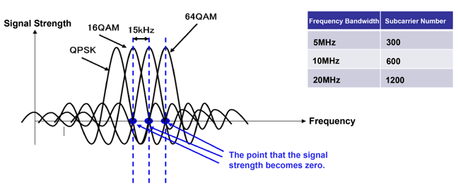
OFDMA (Orthogonal Frequency Division Multiplexing) divides orthogonal frequency and time axis channels (subcarriers) and assigns them to users. Orthogonal means "not interfering with each other," and OFDMA divides the orthogonal subcarriers on the frequency axis so that the signal on each subcarrier is 0 (0 points). This avoids the effects of interference (fading), which can degrade radio quality, and increase the efficiency of frequency use.
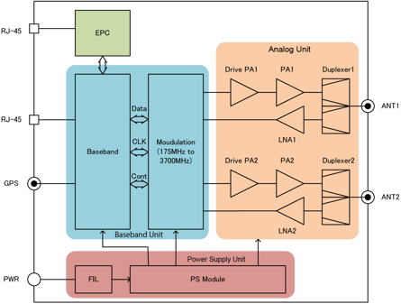
The following image is a JRC Tactical LTE Box block diagram, you can learn more details about it via the following link.
https://www.jrclte.com/jrc-tactical-lte-box
For further information about Private LTE, please check out our other blogs and use cases. If you have any questions, please do not hesitate to contact us.