JRC Tech Seminar Vol.3
In this blog, we will describe OFDM (Orthogonal Frequency Division Multiplexing), which is an important technology in LTE systems.
OFDM (Orthogonal Frequency Division Multiplexing) is a type of multi-carrier transmission. By dividing the information to be transmitted into multiple carrier waves (subcarriers) with different frequencies and sending them together, a large amount of information can be sent at once.
Features of OFDM
1. Multiple carrier waves can be packed into a frequency band for transmission, resulting in high-frequency utilization efficiency.
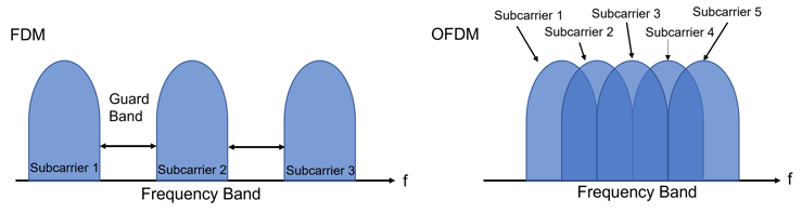 Figure 1: Conceptual diagram of multi-carrier transmission
2. Resistant to interference caused by multipath (radio waves not only reach straight ahead but also propagate through multiple routes by reflecting off mountains, buildings, etc.)
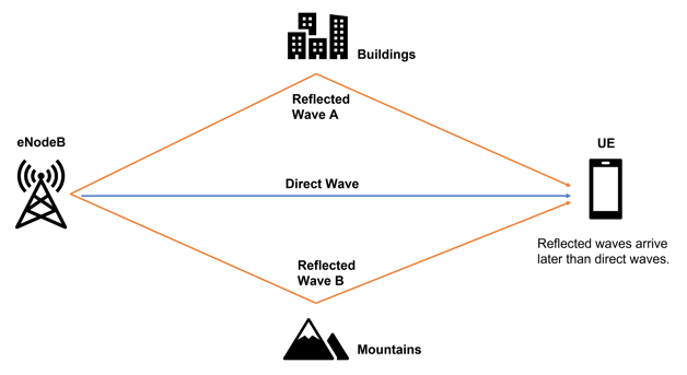 Figure 2: Conceptual diagram of a multipath
What is Spectrum?
A signal whose horizontal axis is represented by the time axis is broken down by frequency, and the horizontal axis is represented by the frequency axis.
The vertical axis represents the signal intensity.
To represent a signal whose horizontal axis is the time axis by a signal whose horizontal axis is the frequency axis, the Fast Fourier Transform (FFT) is performed.
Conversely, to represent a signal whose horizontal axis is the frequency axis by a signal whose horizontal axis is the time axis, the Inverse Fast Fourier Transform (IFFT) is performed.
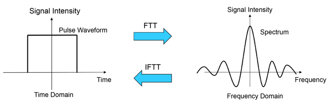 Figure 3: Representation of signals on the time and frequency axes
How to Place Subcarriers in OFDM?
- By placing the peaks of other subcarriers at the frequencies that are the bottoms of the subcarriers (the points where the signal strength becomes zero), it is possible to pack multiple subcarriers into a frequency band while suppressing interference between subcarriers.
- In 3GPP, the interval between the peaks of each subcarrier in LTE is 15 kHz.
- Modulate each individual subcaraaier.
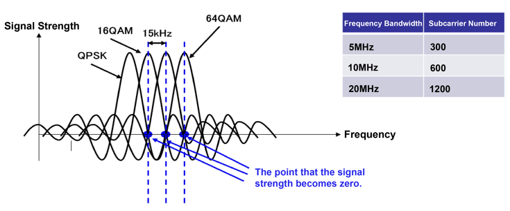
Figure 4: Subcarrier arrangement in OFDM
What is CP (Cyclic Prefix)?
It is a guard interval set in OFDM symbols to suppress the effects of multipath.
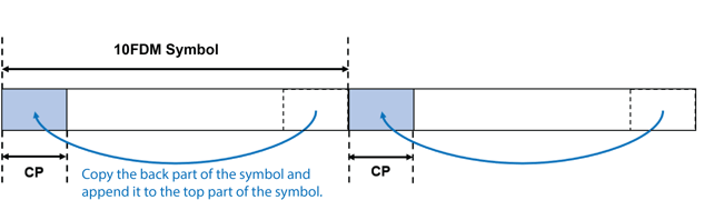 Figure 5: Cyclic prefix
When CP is not set
If the CP is not set, the signal of the reflected wave symbol will be mixed with the direct wave, and interference will occur.
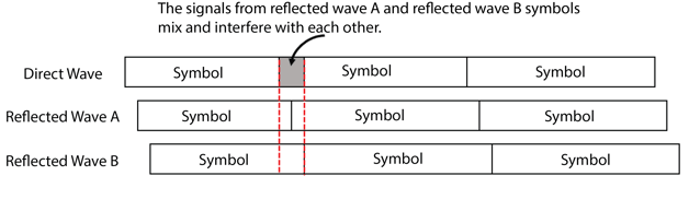 Figure 6: When CP is not set
When CP is set
If the signal of the reflected wave symbol is within the CP set for the direct wave, the effect of interference can be suppressed.
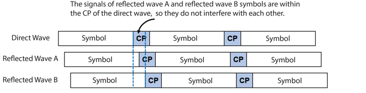 Figure 7: When CP is set
OFDM Processing
- The internal structure of an eNodeB
- An eNodeB can be roughly divided into two units: the radio unit and the control and baseband unit.
- In the radio unit, RF (Radio Frequency) signal transmission/reception processing and modulation/demodulation processing are performed.
- In the control and baseband unit, eNodeB control and conversion between baseband signals and IP packets are performed.
- OFDM processing is performed in the "orthogonal modulation/demodulation unit" of the radio unit.
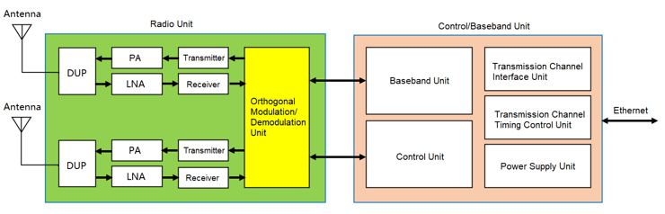 Figure 8: Block diagram of the internal structure of the eNodeB
- OFDM Processing Flow
Figure 9 shows a block diagram of the OFDM processing flow. OFDM processing follows steps (1) through (7) below on the transmitting side. (On the receiving side, the processing is the reverse of the transmitting side.)
- The digital data (baseband signal), which is the transmission data, is input to the "serial-parallel conversion section" as serial data.
- In the serial-parallel conversion section, the bits of data to be transmitted are summarized at once.
- In the subcarrier modulation section, modulation is applied to each subcarrier.
- IFFT processing is performed for each subcarrier.
- Inserts a CP (guard interval) into the OFDM symbol generated by the IFFT process.
- Convert the OFDM symbols, which are digital data, into analog data.
- At last, transmit the signal converted to analog data as an RF signal.
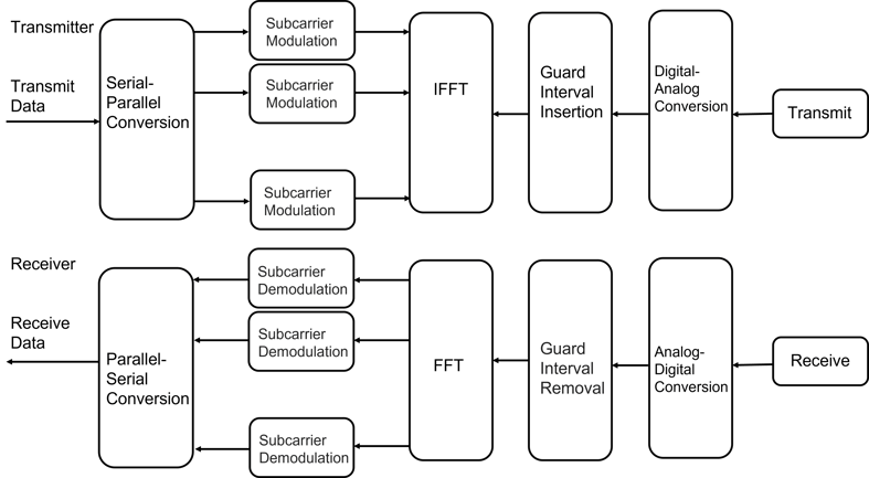 Figure 9: Block diagram of OFDM processing
For further information about Private LTE, please check out our other blogs and use cases. If you have any questions, please do not hesitate to contact us.