
JRC Tech Seminar Vol.4
Hello everyone! We introduced two different frame structure types last time, in this blog, we will talk about Resource Block and Carrier Aggregation, which are two important concepts in LTE frame structure, hope it can help you learn more about LTE.
Resource Block (RB)
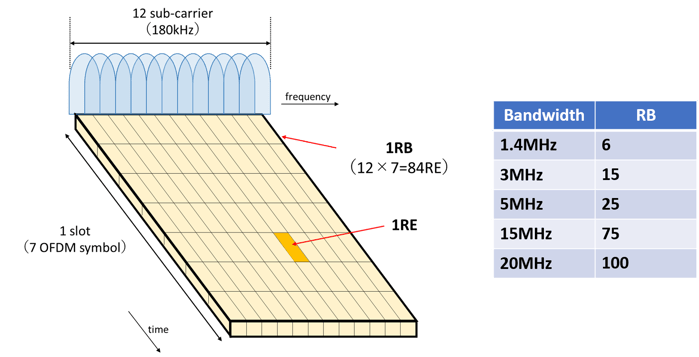
A resource block (RB) is the basic unit of communication, and 1 RB consists of 12 subcarriers (15 kHz between subcarriers) × 1 slot.
One OFDM symbol is called a resource element (RE). The table on the right shows the number of RBs in one slot in each frequency bandwidth.
 Resource Block Overview
① Scheduling
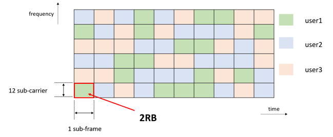
Scheduling is the allocation of RBs by eNBs, to ensure there is no fading effect depending on each user's line conditions. This allocation is performed by the "scheduler", which is part of the MAC layer in the eNB. RBs are defined as 1 slot, but allocation to users is performed in units of 2 RBs. Signals to check the fading status between the UE and eNB for scheduling are measured by the reference signal (RS).
【Step 1】
The UE measures the RS in the DL and feeds back the measurement results to the eNB.
【Step 2】
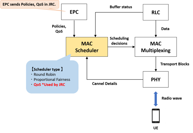
The scheduler performs UE transmission parameter determination and resource optimization by receiving the following information.
1. Receive QoS data from EPC to the scheduler
(Minimum guaranteed bandwidth, maximum allowed bandwidth, packet loss rate, user priority, etc.)
2. Receive information about the radio channel quality (CQI) from the PHY layer.
(Signal strength, noise, adjacent cell interference, etc.)
3. Receive buffer status from the RLC layer regarding data awaiting transmission.
 How the Scheduler Works
There are three types of schedulers: Round Robin, Proportional Fairness, and Max CQI, and each has its own features.
Round Robin:
Fairly schedule and allocate equal resources to all UEs.
The disadvantage is that resources may be allocated to UEs with suboptimal CQI, resulting in lower total throughput.
Proportional Fairness:
Balancing and scheduling between RR and max-CQI. PF considers the fairness of resources and maximizes cell throughput.
PF considers resource equity, performed to maximize the cell throughput.
Qos:
Scheduling based on CQI. Thus, UEs with the highest CQI are scheduled preferentially, thereby increasing overall throughput. The disadvantage is that UEs with low CQI have lower scheduling priority and therefore lack throughput.
【Step 3】
Scheduling assigns an RB to each user as shown in the figure.
 RB Assignment
There are two types of LTE frame structures.
Type 1: Used in LTE FDD
Type 2: Used in LTE TDD
The following text shows the frame structure of each type.
② SR(Scheduling Request)
Scheduling of UL resources is necessary depending on the amount of data to be transmitted by UL. Scheduling UL resources to a UE that has no data to transmit is not particularly meaningful. Therefore, there is a "Scheduling Request (SR)" for the scheduler to recognize the data to be transmitted by each terminal's UL. SR is transmitted on PUCCH.
It is necessary to wait until the time of the scheduling request because data cannot be transmitted by a UE for which UL is not allowed. When this request is received, the scheduler allocates PUSCH resources to the originating UE.
The detailed process is as follows.
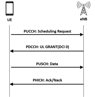
1. The UE sends SR to the eNB through PUCCH.
2. The eNB sends the UL grant (DCI0) through PDCCH.
3. The UE decodes DCI0.
4. The UE sends UL through PUSCH based on the RB specified in DCI0.
5. The eNB decodes the data in the PUSCH.
6. The eNB sends ACK / NACK through PHICH.
7. If the eNB sends NACK, it moves to the retransmission procedure.
Sequence of SR
③ Downlink Control Indicator(DCI)
DCI stands for Downlink Control Indicator and contains the following information.
-PDSCH resource indication, transmission format, and HARQ-related information
-UL grant (PUSCH resource indication, transmission format, and HARQ-related information)
There are various formats for DCI; formats 0 and 4 are used for UL information.
DCI Format
|
DCI Format |
Usage |
|
0 |
UL Grand. Resource allocation for UL data |
|
1 |
DL allocation for SISO |
|
1A |
DL allocation for SISO (compact) |
|
1B |
DL allocation for rank 1 MIMO |
|
1C |
DL allocation for SISO (minimum Size) |
|
1D |
DL allocation for multi-user MIMO |
|
2 |
DL allocation for closed group MIMO |
|
2A |
DL allocation for closed group MIMO |
|
2B |
DL allocation for TM8 (Dual Layer Beamforming) |
|
2C |
DL allocation for TM9 |
|
3 |
TPC commands for PUCCH and PUSCH with 2-bit power conditioning |
|
3A |
TPC commands for PUCCH and PUSCH with 1-bit power conditioning |
|
4 |
UL Allocation for UL MIMO (up to 4 layers) |
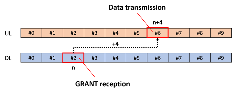
After the UE receives the DCI0, it is not possible to send data by PUSCH immediately due to the decoding of the DCI0 and preparation of the data will be sent.
Therefore, in FDD, data is transmitted by PUSCH in n+4 subframes after DCI0 is received.
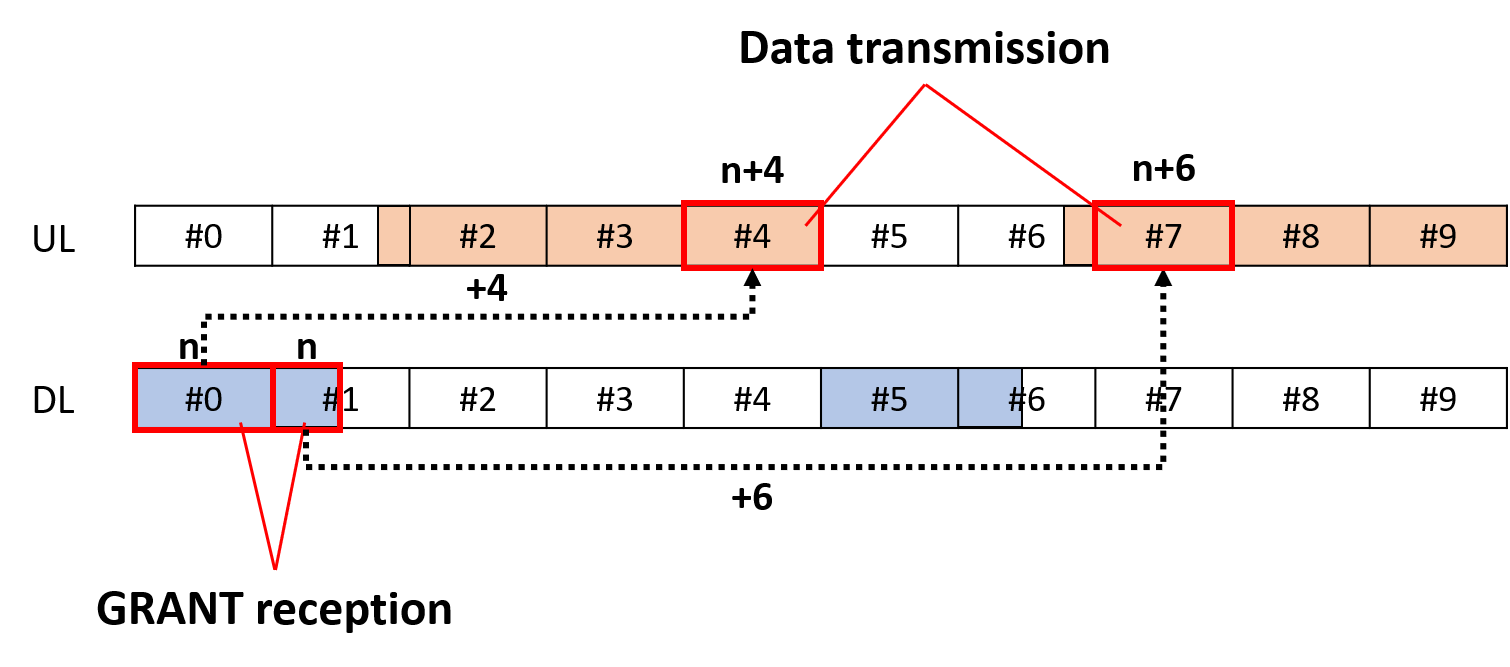
However, in TDD, the timing of DL/UL changes depending on the configuration, and data is transmitted in n+k subframes by PUSCH. This k is as shown in the table below.
FDD's UL Grants
 TDD's UL Grants
DCI0 Configuration List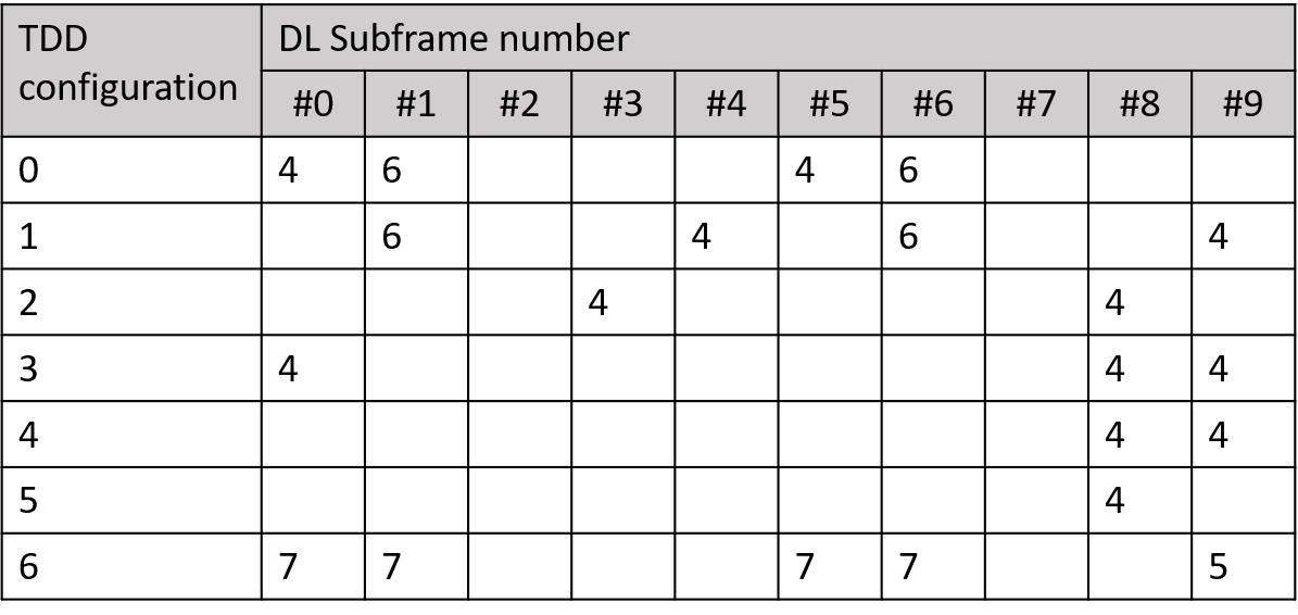
What is Carrier Aggregation?
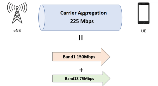
Carrier Aggregation (CA) is a technology that can increase communication speeds by combining multiple bandwidths. 20 MHz LTE carriers can be used simultaneously to communicate with multiple carriers to achieve a wide bandwidth of up to 100 MHz.
 Carrier Aggregation Overview
Depending on the frequency arrangement of the carrier component (CC), CAs are classified into three types.
-Those that use contiguous CCs in a band
-Those that use discontinuous CCs in a band
-Those that use CCs in different bands.
Advantages
(1) Faster communication speeds: Communication speeds in different frequency bands are bundled together.
(2) Stabilization of communication lines: More frequency bands can be used for communication.
3) Improved efficiency of communication lines: Communication can be operated on the better side of the line.
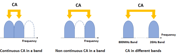 Types of Carrier Aggregation
For further information about Private LTE, please check out our other blogs and use cases. If you have any questions, please do not hesitate to contact us.