
JRC Tech Seminar Vol.2
Thank you for your support of the JRC Tech Seminar, we have released two articles and hope they will be helpful to you. If there are any topics you want to learn, please feel free to contact us, we would also adjust the blog content according to your interest!
We will introduce some basics about radio communication, the seminar will be divided into two parts and in this blog, we will focus on the following five parts.
- What is a Radio Wave
- Radio Wave Propagation
- Power (W, dBm, dB)
- Radio Propagation Design
- Impedance
What is a Radio Wave
An electric field and a magnetic field propagating through space while vibrating.
- Sound is propagated through the air, similar to radio waves.
- Radio waves are similar to light because they do not require a medium (they can propagate without air).
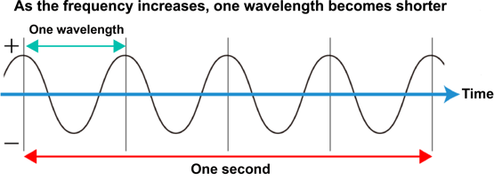
Frequency: Number of vibrations per second (Hz)
Wavelength: Periodic length of a wave (wave motion) (m)
Wavelength (λ) [m] = propagation velocity [m]/frequency [Hz]
Propagation velocity = speed of light = 299,792,458 m/s (300,000 km/s)
e.g. A wavelength with a frequency of 50 MHz is 300[Mm/s]/50[MHz]=6m
| Electromagnetic Wave Name | Frequency Band | Wavelength |
| Ultra-low Frequency (ULF) | ≤3kHz | ≥100km |
| Radio Wave | 3kHz to 3THz | 0.1mm to 100km |
| Infrared | 3THz to 384THz | 780nm to 0.1mm |
| Visible Light | 380THz to 789THz | 380nm to 780nm |
| Ultraviolet | 789THz to 30PHz | 10nm to 380nm |
| X-ray | 30PHz to 30EHz | 10pm to 10nm |
| Gamma-ray | ≥30EHz | ≤10nm |
| Radio Wave Name | Frequency | Wavelength | Main Applications |
| VLF (Very Low Frequency) | 3kHz to 30kHz | 100km to 10km | |
|
LF (Low Frequency) |
30kHz to 300kHz | 10km to 1km | Standard radio wave (radio clock), beacons For marine and aircraft |
| MF (Medium Frequency) | 300kHz to 3MHz | 1km to 100m | AM broadcasting, beacons For marine and aircraft |
| HF (High Frequency) | 3MHz to 30MHz | 100m to 10m | Shortwave broadcasting, marine/aircraft radio, RFID, amateur radio, transceiver toys |
|
VHF (Very High Frequency) |
30MHz to 300MHz | 10m to 1m | FM/TV broadcasting, firefighting/police radio, disaster prevention radio |
|
UHF (Ultra High Frequency) |
300MHz to 3GHz | 1m to 100mm | Specified low power radio, mobile phone, TV broadcasting, LMO, ISM (RLAN, Bluetooth), etc. |
|
SHF (Super High Frequency) |
3GHz to 30GHz | 100mm to 10mm | Microwave relay, satellite communication, satellite broadcasting, ETC, ISM (Radio LAN, UWB) |
| Millimeter-Wave | 30GHz to 300GHz | 10mm to 1mm | Satellite communication, radar, etc. |
| Submillimeter-Wave | 300GHz to 3THz | 1mm to 100㎛ | Radio astronomy |
Radio Wave Propagation
By creating an electric potential difference in space, a radio wave (electric field) proportional to the voltage is radiated.
The strength of the radio wave emitted from the antenna is called Transmitting power (W).
Radio wave propagation: Radio waves travel through the air and reach a distant place.
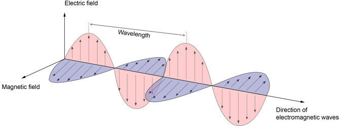
The direction in which the electric field vibrates is called polarization.
Power (W, dBm, dB)
dBm means that 1mW is expressed as 0dBm.
Relationship between 1mW and 0dBm:
D=10log10P
P=10(D/10)
P is Mw, D is dBm
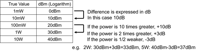
The dB is not a unit of absolute value or quantity, but a relative unit of ratio or magnification.
Radio Propagation Design
Perform desk calculations to determine if wireless communication is feasible. (Can the required service area be secured?)
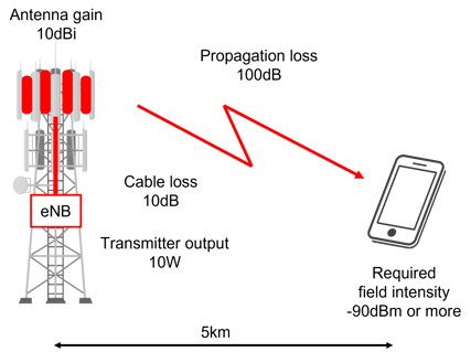
| Item | Value | Calculated value |
| Transmitter output | 10W | 30dBm |
| Cable loss | 10dB | 20dBm |
| Antenna gain | 10dBi | 30dBm |
| Propagation loss | 100dB | -70dBm |
| Required field intensity | -90dBm | -70dBm |
| Margin | 20dB |
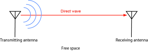
Free space loss: Virtual space with nothing in it. Since no reflection occurs, the received power attenuates with the square of the theoretical distance.
When there is no obstacle, antenna height is high, and there is no influence of buildings, etc.
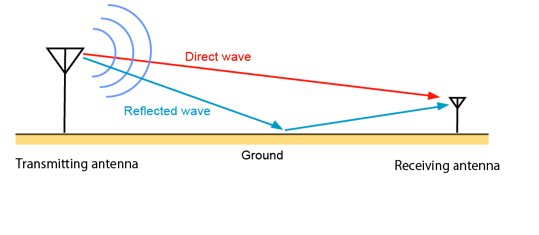
Two-wave model: A space where there is plane earth that is totally reflected. At the receiving point, two waves (direct wave and earth-reflected wave) arrive and interfere with each other.
At the point where the direct wave and the reflected wave are in opposite phases, they cancel each other out and the received power becomes small (dead point).
The point where the received power drops often occur in the vicinity of a few meters.
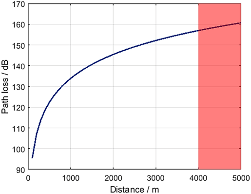
Okumura - Hata Model: This is an approximate curve (model) created based on aggregate data from actual measurements of radio propagation characteristics of wireless devices in different environments (open areas, suburbs, small and medium-sized cities, and large cities) during the development stage of mobile radio (car phone) and cellular. It was used in the construction of cell phone networks and is still widely used today.
 Source: https://link.springer.com/article/10.1007/s00502-018-0639-y
The possible approximation conditions:
- Frequency f (MHz): 150 MHz to 1.5 GHz
- Communication distance d(m): 1 km to 20 km
- Antenna height of base station hb(m): 30 m to 200 m
- Antenna height of mobile station hm(m): 1m - 10m
It is intended for use over medium to long distances, so the difference becomes large when the distance between wireless devices is as short as several tens of meters.
Impedance
What is Impedance?
DC Circuit: Resistance is the only component that makes it difficult for electricity to flow.
AC Circuit: resistance, capacitors, coils → the quantity that expresses the difficulty of current flow is called "impedance".
Resistance: In both DC and AC, a voltage drop occurs when current flows through a resistance. In AC, the value of the voltage drop is the same even if the frequency of the signal changes.
Coil: A coil is a coil of wire, so in DC, even if current flows through it, there is almost no voltage drop. However, in the case of AC, the higher the frequency of the applied signal, the larger the value of the voltage drop.
Capacitors: In DC, no current flows. In AC, the higher the frequency of the applied signal, the smaller the value of the voltage drop.
Characteristic Impedance
Radio equipment, cables, and antennas have a characteristic impedance, which is expressed as Z=R+jX. However, the jX part is not shown for convenience.