JRC Tech Seminar Vol.7
Hello everyone! This is the second part of the LTE Protocol Stack, this time we will mainly introduce the C-plane, which is used to control the EPS session, the roles of each layer, and the protocol stack in 5G.
Here you can read the first part by following the link:
https://www.jrclte.com/blogs/lte-protocol-stack-part-1
C-plane
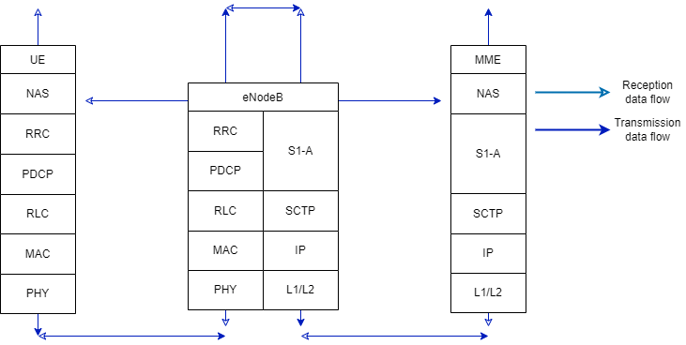
Figure 7 About C-plane
RRC and NAS are added in addition to U-plane in the protocol stack that controls data communication.
The eNodeB communicates with the Mobility Management Entity (MME) instead of the S-GW.
The roles of protocols belonging to the C-plane but not to the U-plane are described below.
(1) NAS (Non-Access Stratum)
Role: Authenticates communication between the UE and the EPC (core network)
Layer 3
(2) RRC (Radio Resource Control)
Role: Controls resources between the UE and the eNodeB through a switch
Layer 3
(3) SCTP (Stream Control Transmission Protocol)
Role: Summarizes the advantages of TCP and UDP
Layer 4
Roles of Each Layer
- Layer 1 (Physical Layer)
The Physical Layer is located at the first layer of the protocol stack and is used for transmitting data received from the terminal to the upper layers and for transmitting data received from the upper layers to the terminal.
- Layer 2 (MAC, RLC, PDCP)
The roles of Layer 2 are shown in the table.
|
Sublayer Name |
Role |
Image |
|
MAC |
Connecting the logical channel to the transmission channel |
|
|
Multiplexes or inverse multiplexes MAC SDUs (Service Data Units) of the logical channel to create or decode TBs (Transport Blocks) of the transmission channel |
Figure 3-6 |
|
|
Reporting scheduler information |
|
|
|
Error correction by HARQ (Hybrid ARQ) |
|
|
|
Priority control between logical channels of a single UE |
|
|
|
RLC |
Error Correction with ARQ in AM (response mode) data transmission |
|
|
Decomposition and assembly of RLC SDUs in UM (non-response mode) and AM data transmission |
Figure 3 |
|
|
PDU (Packet Data Unit) repartitioning in AM data transmission |
Figure 3 |
|
|
Rearrangement of PDUs in UM (non-response mode) and AM data transmission |
Figure 3 |
|
|
PDCP (U-plane) |
Header Compression and Decompression |
Figure 3, 4 |
|
User Data Transmission |
Figure 2 |
|
|
Sequential transmission of upper layer SDUs in RLC AM |
|
|
|
Double detection of lower layer SDUs in RLC AM |
|
|
|
Retransmission of PDCP SDUs during handover in RLC AM |
|
|
|
PDCP (C-plane) |
Encryption and Integrity Protection |
|
|
Control plane data transmission |
Figure 7 |
- Layer 3 (NAS, RRC)
The RRC layer controls the UE and has two states for this purpose: RRC_Connection and RRC_Idle.
Functions include notification (reception of MIBs and SIBs 1-13), paging (virtual address assignment), RRC connection control (state management), security (NAS layer), radio bearer management, mobility (handover), and QoS (user priority control).
Unlike the previous layers, the NAS layer does not communicate with the eNB but controls authentication with the EPC (MME).
It also performs concatenation with RRC layer messages when authenticating with the MME.
*Not performed in case of unusual contention-free based.
About 5G
The points that will change in 5G include C/U separation, changes in C-plane RRC status, etc.
(1) C/U separation
One of the problems with 5G is that frequent handovers (switching the gNB connected to the UE) occur, resulting in a decrease in throughput.
Therefore, U-plane, which always uses the fastest path for data communication, is performed by 5G base stations (gNBs), while C-plane, which controls routing, is performed by 4G base stations, which is called C/U separation.
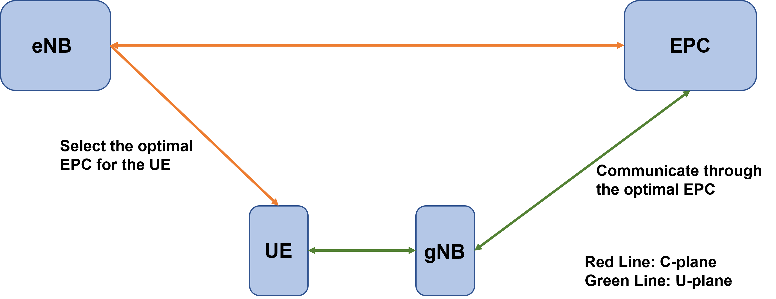
Figure 8 U/C Separation
(2) Variation of RRC state
In LTE, there were only two states, RRC-IDLE and RRC-CONNECTED.
RRC-INACTIVE is added as an intermediate state in 5G, which will realize power saving.
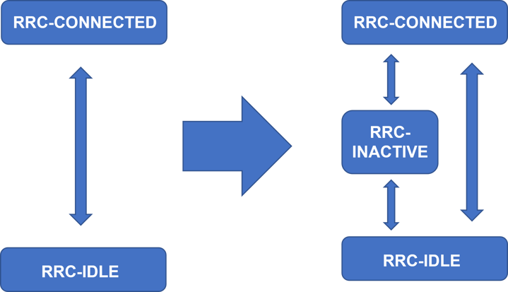
Figure 9 Additional RRC states in 5G
For further information about Private LTE, please check out our other blogs and use cases. If you have any questions, please do not hesitate to contact us.