
JRC Tech Seminar Vol.5
Hello everyone, in this seminar we will describe how the UE attaches to the eNB: The UE first performs cell search and synchronizes DL with the eNB. Then synchronize UE and the UL of eNB by random access, establishing the RRC.
We will divide the contents into two parts, in this part we will explain Cell Search and the System Information of the Cell in detail, hope you will be interested!
For additional information about LTE Attach, please refer to our other blogs by clicking the links below.
https://www.jrclte.com/blogs/jrc-tech-seminar-vol.1
https://www.jrclte.com/blogs/jrc-tech-seminar-vol.1-lte-attach-sequence-procedure-part-2
Cell Search
The following two procedures are required when UE connects to eNB.
- Detecting and synchronizing cells in the network
- Receiving and decoding information is called "cell system information", which is necessary for communication within a cell.
These procedures are called "cell search".
Terminals do not perform cell search only after power-on, but also during handover (cell re-selection), which is performed by comparing the reception quality of neighbor cells.
① PSS(Primary synchronization signal) and SSS(Secondary synchronization signal)
Two signals, PSS (primary synchronization signal) and SSS (secondary synchronization signal) are used by the UE to synchronize frames. The position of PSS and SSS within a frame varies depending on FDD and TDD.
・FDD
PSS is transmitted on the last symbol in the first slot of subframes 0 and 5, and SSS is transmitted on the second-to-last symbol in the same slot.
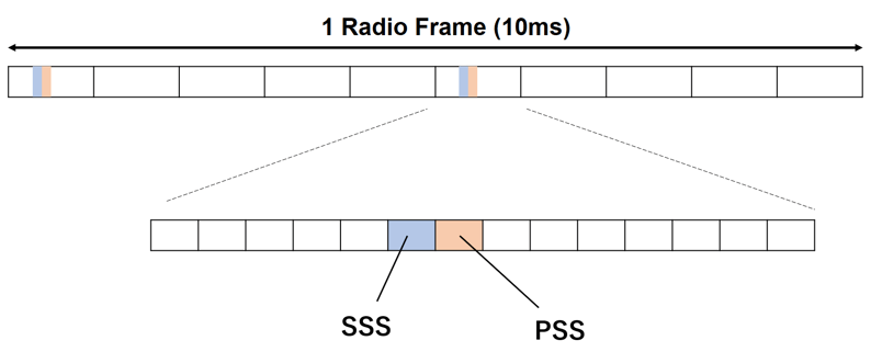
Configuration of PSS and SSS in FDD
・TDD
PSS is transmitted in the third symbol of subframes 1 and 6, and SSS is transmitted in the last symbols of subframes 0 and 5.
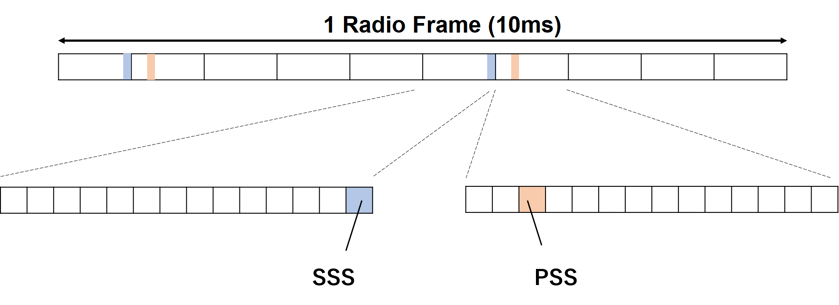
Configuration of PSS and SSS in TDD
When the UE detects the PSS, the following information can be obtained.
- The 5ms timing of the cell and the location of the SSS.
- Physical layer Cell Identifiers in the Physical layer Cell Identifier group. The Physical layer Cell Identifier group is narrowed down from 504 to 168.
From this PSS detection, the location of the SSS is specified, with the reception of the SSS
The UE will obtain the following information.
- The timing of the frame
- Physical layer Cell Identifier group (specified from 168)
In addition, the two SSSs in the frame need to be different to determine the frame timing.
② Physical layer Cell Identifier (PCI)
A total of 504 different physical layer cell identifiers are defined in LTE. These are divided into 168 cell identifier groups, each group containing three cell identifiers.
| PCI | 0 | 1 | 2 | 3 | 4 | 5 | … | 30 | 31 | 32 | ... | 502 | 503 | 504 |
| Cell Identifier Group ID | 0 | 1 | ... | 10 | ... | 168 | ||||||||
| Cell Identifier ID in Group | 0 | 1 | 2 | 0 | 1 | 2 | ... | 0 | 1 | 2 | ... | 0 | 1 | 2 |
Configuration of PCI
System Information of the Cell
Once the UE can synchronize with the eNB's cell through cell search, it then obtains the system information of the cell.
The system information of the cell is repeatedly reported by the eNB. The system information includes the cell's bandwidth for DL and UL, the configuration of DL and UL in case of TDD, and detailed parameters about the random access procedure.
The system information is transmitted by MIB and SIB.
① MIB (Master Information Block)
It is transmitted via PBCH.
It consists of very limited system information and is sent to the UE to read the information in the SIB.
The MIB contains the following three pieces of information
-DL bandwidth information (for DL synchronization)
-Configuration of PHICH
-SFN
One BCH transport block corresponding to the MIB is transmitted once every 40 ms.
The encoded BCH transport block is mapped to the first subframe of each of four consecutive frames. The BCH is not mapped on an RB base and is transmitted in the first four OFDM symbols of the second slot of subframe 0 and only on the 72 central subcarriers.
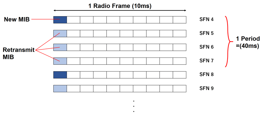
MIB Mapping Information
- SFN (System Frame Number)
SFN is from 0~1023 and increases by 1 when it reaches subframe 9. The UE and eNB cannot exchange information unless the time is the same, so the subframe and SFN must be aligned. 1 frame adds up to SFN. Therefore, the SFN period is 10,240 ms.
From the image below, the PSS/SSS will synchronize the subframes and the MIB will synchronize the SFN. This allows DL synchronization between the UE and eNB.
| Name | Range | Synchronization method |
| Subframe | 0 to 9 | PSS/SSS |
| SFN | 0 to 1023 | MIB |
Role of Subframe and SFN
② SIB (System Information Block)
SIBs are transmitted by PDCCH and contain the main part of the system information of the cell. there are 16 types of SIBs and the system information sent by each SIB is different. MIBs and SIBs are repeatedly reported, with lower-level SIBs (SIB1) being sent more frequently.
SIBs 1 and 2 are always sent, and SIB1 is sent every 80 ms in subframe #5. Other SIBs are sent according to the scheduling information sent in SIB1.
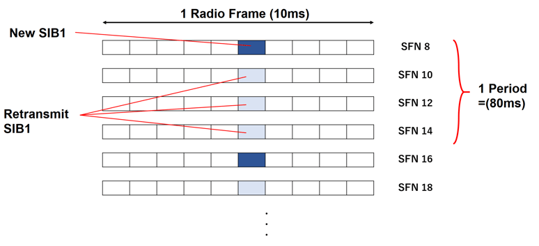 SIB1 Mapping Information