
JRC Tech Seminar Vol.4
This time we will explain the signal transmission technology of LTE in radio frames. The contents will be divided into two parts and in this part, we will focus on the frame structure of LTE. Hope you will like it!
What is FDD/TDD?
FDD is called frequency-division duplexing, in which communication is performed in different frequency bands for transmission and reception.
Feature: Simultaneous UL/DL transmission is possible, however, requiring two frequency bands.
 FDD Overview
TDD is called time-division duplexing, in which communication is performed at different times for transmission and reception.
Feature: Communication can be performed in one frequency band, but simultaneous UL/DL transmission is not possible.
 TDD Overview
Frame Structure
There are two types of LTE frame structures.
Type 1: Used in LTE FDD
Type 2: Used in LTE TDD
The following text shows the frame structure of each type.
Frame Structure Type1
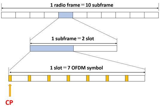
A radio frame (10 ms) consists of 10 subframes (1 ms). A subframe consists of two consecutive slots (0.5 ms); one slot consists of seven OFDM symbols.
 LTE Frame Structure Type1
What is CP?
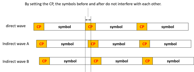
CP (Cyclic Prefix) is a mechanism to eliminate the effects of multipath (radio waves arriving through multiple different paths due to reflections, etc.). Setting CP at the beginning of a symbol will suppress interference between symbols.
 CP Overview
Frame Structure Type2
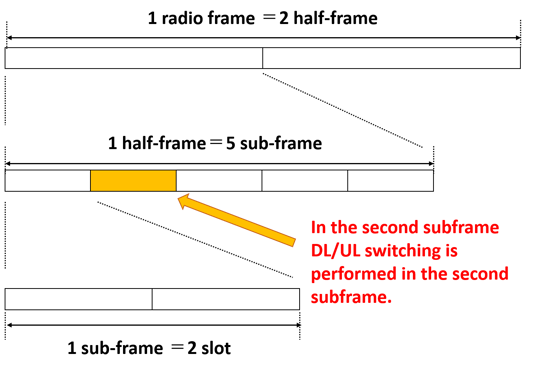
The radio frame length is 10 ms and is divided into two half frames. Each half-frame consists of five subframes (1 ms). Each subframe consists of two slots. In TDD, DL/UL switching is performed, and the frame to be switched is called SS (special subframe).
 LTE Frame Structure Type2
Frame Structure Type2 Configuration
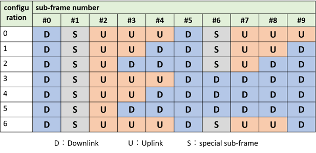
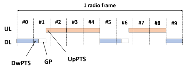
There are seven different Type 2 frame structures as shown in the figure, which can be changed flexibly. Subframes #0 and #5 are always assigned to DL, and subframe #2 is always assigned to UL. Frame structure 2 is commonly used.
 Frame Structure Type2 Configuration
Special Subframes
The special subframe (SS) is the frame that switches from DL to UL. This SS is divided into three parts: a Downlink Pilot Time Slot (DwPTS), a Guard Period (GP), and an Uplink Pilot Time Slot (UpPTS). The shorter the switching time, the more data can be sent.
DwPTS: It is treated as a standard DL subframe, but the amount of data transmitted is reduced.
GP: Used to control DL to UL switching.
UpPTS: Not used for data transmission, because it is a very short section.
 GP Overview
Cell Radius
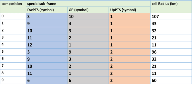
SS has 10 different subframe configurations as shown in the table below, each with different OFDM symbols for DwPTS, GP, and UpPTS. If the DwPTS is not higher than 9, DL data cannot be transmitted, and if the DwPTS is lower than 9, the frame is empty with no data transmission.
This SS allows the guard period to be shortened and the data extension part to be enlarged to gain as much throughput as possible. Conversely, it can be designed to sacrifice the amount of throughput and have a wider guard period.
Example: Cell radius for SS frame 0
The GP in Frame 0 has 10 OFDM symbols. In this case, the GP time is
(10/14)/1000 [s]= About 0.000714 [s]
Since the RF signal travels at the speed of light C = 3.0 × 10^8 m/s, the distance is
0.000714 [s] × 3.0 ×10^8 [m/s] = 214 [km] (214000 [m]
(This is a round-trip distance.) Therefore, the cell radius is 107 km.
 Type of SS
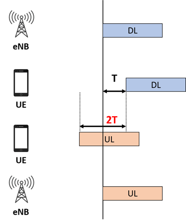
TA(Timing Advance)
Depending on the distance of different UEs, the timing of ULs arriving at the eNB will be different. Therefore, the eNB measures the arrival time of the received UE signals and controls the UL timing so that they arrive at the eNB at the same time. This control is called TA (Timing Advance), and the MAC layer of the eNB generates TA commands. The TA command is sent to the UE in the DL-SCH, and the MAC PDU of the TA command is shown in the figure below.
 Timing Advance
The total length is one byte, and the first two bits are pre-reserved and set to 0. The remaining 6 bits contain the TA value (0~63).
 The MAC PDU of the TA command