
JRC Tech Seminar Vol.0
In the last chapter, we have introduced the definition of the LTE system, its features, basic components, and some related content. Were they simple enough to understand? This time we will focus on things about "throughput" in LTE. It would be the second and last part of Vol. 0. Hope you will like it!
What is Throughput?
Throughput refers to the speed of communication and is defined as the amount of data that can be transferred per unit of time by a communication device. The amount of data that can be transferred per unit of time is expressed in "bps". For example, if one megabit of data is transferred per second, the throughput is expressed as 1Mbps (Megabit per second).
Theoretical throughput and effective throughput
There are two types of throughput: theoretical throughput and effective throughput.
Theoretical throughput refers to the amount of data that can theoretically be transferred per unit of time, and it includes not only user data but also all data such as header information for transferring data. Effective throughput refers to the amount of data that can actually be transferred per unit of time and includes only user data, excluding header information.
Main factors that affect throughput
- frequency bandwidth
- modulation method
- MIMO
- distance between eNodeB and UE
- UE category
- number of simultaneous users
- data retransmission
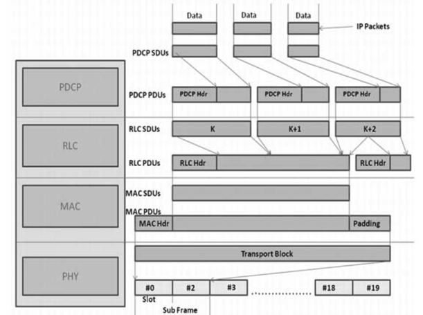
When data is transmitted, it is processed in order by a structure called layers.
 Source: https://www.hebergementwebs.com/lte-tutorial/lte-layer-data-flow
For example, when sending IP packets such as user data from an eNodeB to a UE, the data is processed in order from the top layer. At this time, information called a header is attached to the user data and sent to the next layer.
The data processed in each layer in turn is called a "transport block" in the MAC layer. This transport block contains the user data, the header information of each layer, and the system information (MIB and SIB) of the eNodeB. The transport block sends the header information, MIB, and SIB which are excluding system information as user data.
Throughput is defined for each layer. Throughput in the PHY layer and MAC layer is defined as: In addition to user data, header information and eNodeB system information are included, and this is defined as the theoretical throughput.
On the other hand, the throughput in the IP layer is the throughput required to send only the user data, excluding the header information and the eNodeB system information, and this is defined as the effective throughput.
FDD
| Layer | 5MHz | 10MHz | 20MHz |
| IP |
34.9.9Mbps/11.5Mbps |
71.7Mbps/24.3Mbps |
146Mbps/49.9Mbps |
|
MAC |
37.5Mbps/12.5Mbps |
75Mbps/25Mbps |
150Mbps/50Mbps |
|
PHY |
37.5Mbps/12.5Mbps |
75Mbps/25Mbps |
150Mbps/50Mbps |
TDD
| Layer | 5MHz | 10MHz | 20MHz |
|
IP |
21.3Mbps/1.5Mbps |
44.5Mbps/3.5Mbps |
92Mbps/7.9Mbps |
|
MAC |
27.5Mbps/2.5Mbps |
55Mbps/5Mbps |
110Mbps/10Mbps |
|
PHY |
27.5Mbps/2.5Mbps |
55Mbps/5Mbps |
110Mbps/10Mbps |
Factors Affecting Throughput
Frequency Bandwidth
As the bandwidth increases, the amount of data that can be sent at one time increases, resulting in faster communication speed.
For example, in FDD, when the bandwidth doubles, the communication speed (throughput) also doubles. In the case of TDD, in addition to the bandwidth, the throughput is determined by the ratio of Downlink to Uplink communication time.
In LTE's OFDMA scheme, a block of 12 subcarriers (180 kHz) separated by 15 kHz is called a resource block. The data to be sent to the user is allocated in these resource blocks.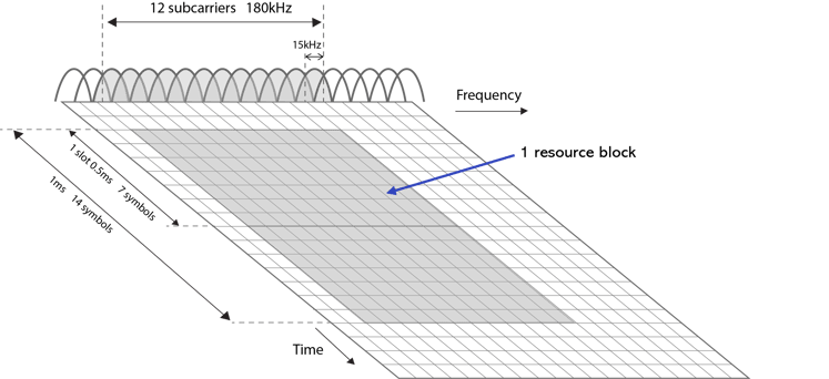
The wider the frequency bandwidth, the larger the number of subcarriers and the larger the number of resource blocks that can be used, thus increasing the communication speed (throughput).
| Frequency bandwidth | Number of subcarriers | Number of resource blocks |
| 5MHz | 300 | 25 |
| 10MHz | 600 | 50 |
| 20MHz | 1200 | 100 |
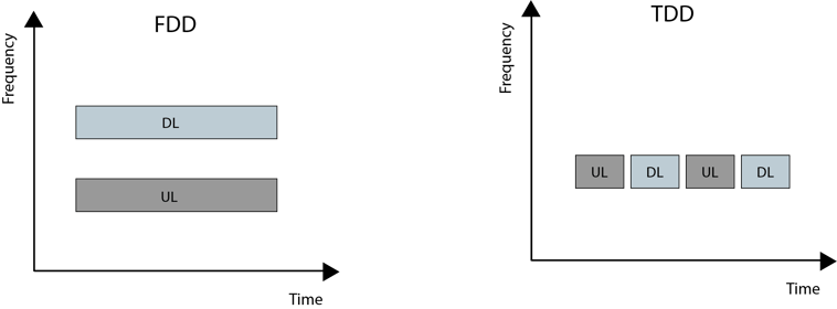
FDD and TDD communication methods
In FDD, Downlink and Uplink can communicate at the same time because Downlink and Uplink use different frequencies for communication.
In TDD, Downlink and Uplink use a single frequency for communication. Therefore, the time for communication between Downlink and Uplink is separated.
TDD DL/UL communication time switching
In TDD, communication time between Downlink and Uplink is switched in one frequency.
The figure on the left shows the allocation of transmission time for Downlink and Uplink as specified in 3GPP Release 8.
The gray color indicates the transmission time allocated to Downlink, and the green color indicates the transmission time allocated to Uplink.
The orange color is called "Special Subframe" and is the time to switch from Downlink to Uplink.
In TDD, the communication time between Downlink and Uplink is switched based on this 3GPP standard.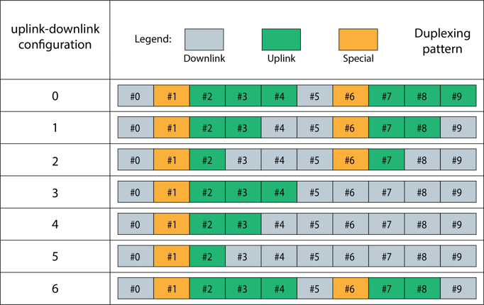
FDD Band3 Throughput Curve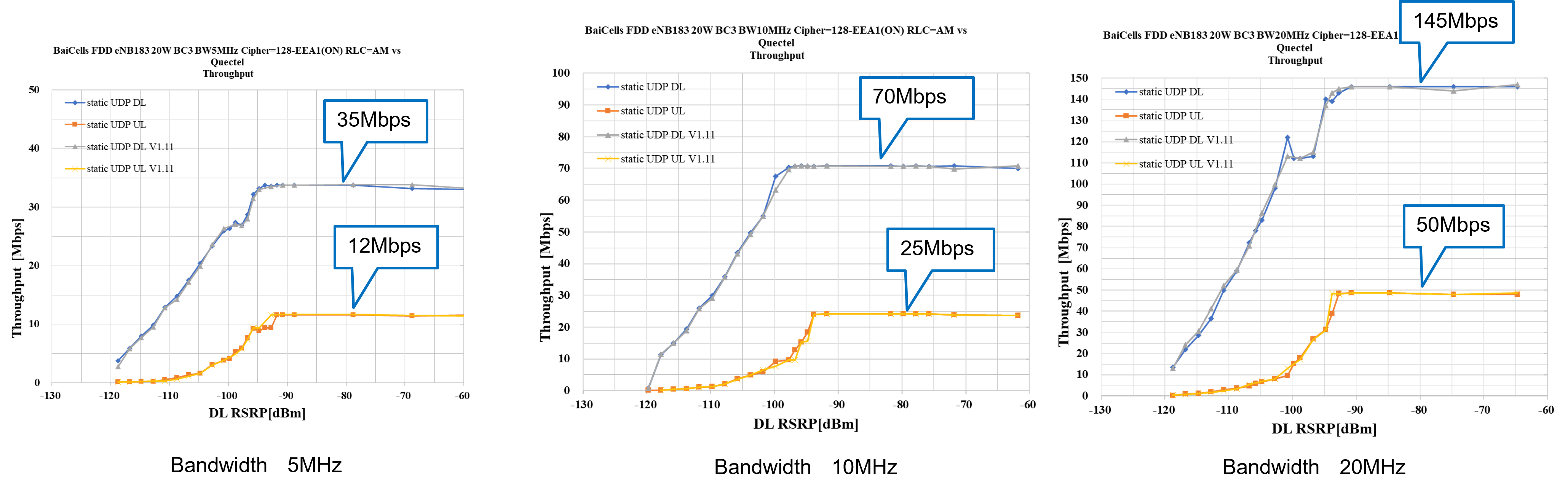
Compared to the throughput with a bandwidth of 5MHz, a bandwidth of 10MHz can produce about twice the throughput, and a bandwidth of 20MHz can produce about four times the throughput.
TDD Band38 Throughput Curve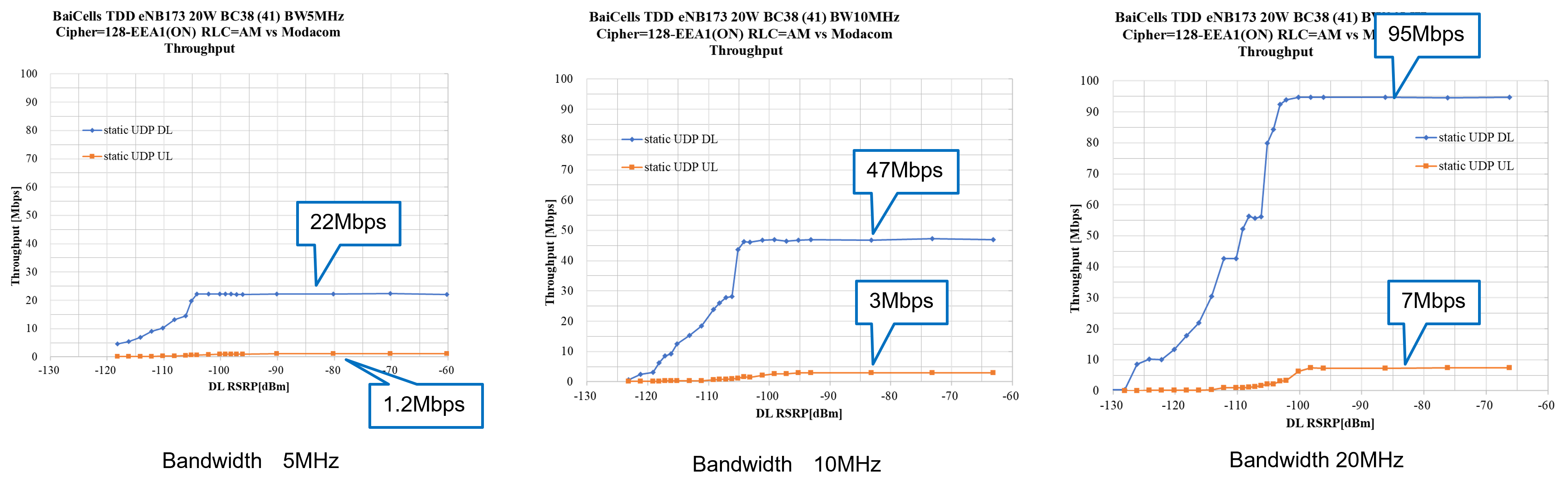
As with FDD, if the bandwidth is doubled, the throughput can also be doubled in speed.
The reason why the throughput of Downlink and Uplink is lower than that of FDD is that the transmission time of Downlink and Uplink is switched on one frequency.
Modulation method
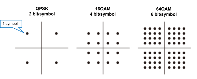
The amount of data that can be sent at one time varies depending on the modulation method. Modulation refers to the conversion of digital signals represented by 0 and 1 into analog signals.
For example, QPSK (Quadrature Phase Shift Keying) sends two bits of information in one symbol, while 16QAM (Quadrature Amplitude Modulation) can send four bits, and 64QAM can send six bits.
By sending more data at a time, the communication speed becomes faster.
In LTE, the modulation method is changed according to the reception status of the UE.
For example, when the reception is good, it uses 64QAM, but when the reception is bad, it uses 16QAM or QPSK to send data to avoid data errors.
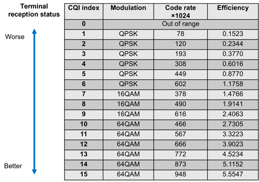
CQI and Modulation Method
In LTE, there is a parameter called CQI (Channel Quality Indicator) that determines the modulation method.
This parameter indicates the quality of the reception that the UE sends to the eNodeB, and as shown in the table below, each CQI parameter determines which modulation method the eNodeB uses to send data.
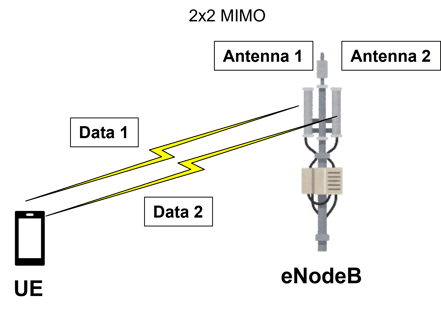
MIMO
MIMO, which stands for Multiple-Input and Multiple-Output, is a technology that uses multiple transmit/receive antennas to transmit/receive data over multiple paths (channels).
The more paths (channels) that can be used to send and receive data at once, the more data can be sent and received per unit of time, and the higher the throughput can be.
There are two types of MIMO: 2x2 MIMO and 4x4 MIMO.
In 2x2 MIMO, two antennas are used to transmit separate data, which can result in twice the transmission speed than without MIMO.
On the other hand, 4x4 MIMO allows four antennas to transmit separate data, which is four times faster than without MIMO.
Distance between eNodeB and UE
There is a parameter called RSRP (Reference Signal Received Power) that indicates the radio wave level depending on the distance between the UE and the eNodeB.
Basically, an area with a coverage of -100dBm to -110dBm RSRP is considered to be the attach limit (the limit of the area for a UE to connect to an eNodeB). When the RSRP is above -110dBm (e.g. -115dBm), the UE cannot attach to the eNodeB. (*But it depends on the setting of the eNodeB)
Since the transmission power of the eNodeB is constant, the farther the UE is from the eNodeB, the weaker the signal (lower RSRP) and the lower the throughput.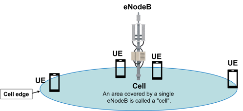
[Reference]Parameters related to the received signal
The parameters that represent the signal received by a UE from an eNodeB include parameters that represent the strength of the received signal and parameters that represent the quality of the received signal.
- Parameters indicating the strength of the received signal (RSRP and RSSI)
-RSRP is an abbreviation for "Reference Signal Received Power".
It is a parameter that indicates the reception level of the reference signal transmitted from the eNodeB.
-RSSI is an abbreviation for "Reference Signal Strength Indicator".
This is a parameter that includes all of the received signal levels + noise + interference.
- Parameter indicating the quality of the received signal (RSRQ)
-RSRQ is an abbreviation for "Reference Signal Received Quality", a parameter that indicates the quality of the received signal.
RSRQ is expressed by the following equation.
RSRQ = N x RSRP / RSSI (N: number of resource blocks)
For example, even if the distance between the UE and the eNodeB is close and the RSRP is high, if the influence of noise and interference is strong, the communication becomes unstable and the received signal quality becomes worse.